Automatic DC System
To build full automatic dust collection system.The first consideration
is how to detect the running of woodworking machines.
In case of ECOGATE, ONEIDA, JDS, P.S.I. e.t.c. they need multiple signal
wiring from each machines to the dust collector controller
If you can find the machine current detecting point(A) or (B) on picture
"HOME AC LINE THEMATIC",you are very lucky no need these wirings.
HOME AC LINE THEMATIC
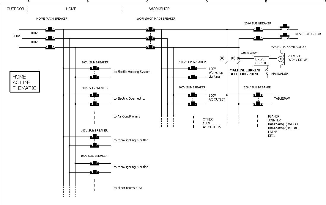
In Japan,the power line is feeded in as "sigle phase, 3wires".On the thematic,outer couple of wires is 200V and inner couples are 100V each. I use 200V for stationary woodworking machines and detect machine running by AC current sensor at the point"machine current detcting point(A or B)"
AC current sensor (same principle with measuring instruments - AC clamp meter e.t.c.)is a small electric part. Some are through wire hole,others clamp type.
http://www.u-rd.com/english/index.html
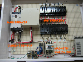
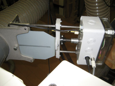
My workshop AC power distributer and a current sensor
It generate a little AC voltage according to value of detecting AC current,then
amplify and rectfy this signal and drive a magnetic contactor(5HP) to switch
on the dust collector.So the dust collector is automatically power on by
any machine running. and power off when machine is switch off(in my case
5A or more to work).
A few type of sensitive sensor generate 2-3V at 10A, it drives a kind of
SSR(solid state relay, ofcourse with handling power of your dust collector)
directly by simply rectfying signal to DC voltage),no need complex circuit.
note: current sensors have maximum detecting current value.
From another point of view, It may be done now at your workshop simply
by a new AC cable from the shop main braker to the dust collector to divide
lines.When you are going to build or rebuild your workshop, this might
be worth to consider.
The experimetal test
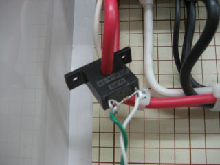
I have an AC current sensor and used it for the dustcollector control.The
parts above is U-RD CTL-6-S-H with 5.8mm dia. hole.I set this at the machine
current detecting point. Though my control circuit is somewhat complexed
with a few IC's, I tested an idea to simplfy the circuit.That is to use
the current sensor as a small DC voltage source.
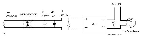

On the circuit diagram above, CT(current transformer) is an AC current
sensor and arrow line represents the AC power line wire. ZD is a dc voltage
stabilizer keeping the dc votage at 5V max when machine's rush current
flows at starting. Shotkey diode is desirable to detect a small signal
with their low voltage loss.
I runned machines and measured 2.8VDC at 6.8A and 3.2VDC at 8.6A.
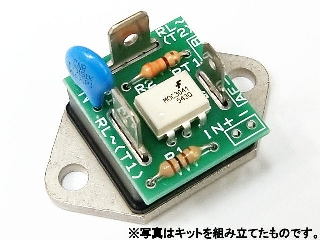
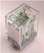
This picture is a parts kit of SSR(solid state relay) sold in Japan which
swiches 100V 35A AC. The control input is 3-8V DC 5mA. So with the higher
current than this test ,that circuit can drive this SSR replacing 470 ohm
resistor.
If you use other types of currnt sensor with bigger hole, adding extra
1 turn(total two turns)in the hole ,can maintain nearly double value of
DC voltage. It means with lesser current, it will work.
Sorry, I can't know elctoric parts market in U.S, be unable to suggest actual parts.
Note1: I did test with induction motors, I don't know about kinds of power
tools which have variable speed control by pulse wave.
Note2:That kit needs a heat sink when used 2A or more high current.
Automatic Blastgate
If you cann't find "machine current detection point", my automatic
blastgates can activate the dust collector by wiring.
I tried to build with less number of parts.
CIRCUIT DIAGRAM
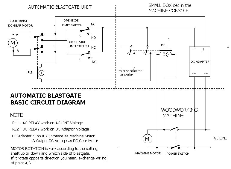
You need to pull out two AC cables from the machine switch assembly. I
put a DC adapter and a Relay(RL1) in the small plastic box and fix inside
of the console to prevent dust and accidents.In this way, wires(or a three
wire cable) pulled outside from the machine treats low DC voltage only.
It works stand alone with a woodworking machine.
MAIN PARTS DISCRIPTION
| DC GEAR MOTOR |
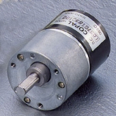 |
DC Gear Motor made by "COPAL"
DC 24V 0.3A
It was used one ,so I don't know detail.
Specs may be
Gear Ratio 1:500
12rpm
Torque 50mN/m
When Dustcollector works,the sunction power pull the shatter,
and some blastgates don't move smoothly by the sharp edge of shatter,so
the motor may need fairy power. |
| LIMIT SWITCHES |
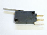 |
A little micro switch wth hinge lever.
contact current 5A max |
| RELAYS |
 |
A little power Relay made by "Panasonic".
Double "make" and "break" contact points(1A or more).
In my case one works on 200VAC and another on 24VDC |
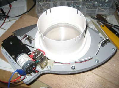
Construction
The left picture is view of one automatic blastgate.The manual blastgate
is 4" alminium made purchased from Leevalleytools.
The base is a plastic sheet 6mm thick. and hold by the two fixing screws
at original screw holes(chaged to longer one)
The clank with long hole is set on the motor shaft.the shatter has a lod(6mm
dia.) whitch is inserted into the clank hole.
The relay(RL2) and limit switches are placed on the down side of the base.
As the motor rotation, the shatter is pulled or pushed by this mechanism.
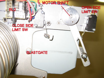
This is the down side view.
At this moment, the shatter is open and the clank push the openside limit
switch lever so that motor don't rotate further more.
You can see the small bottun on the top of the close side limit switch
lever. I couln't place this switch at the desireble position,becuse of
the base holding screw .
So I add the bottun so that clank push this close side limit switch lever
when the shatter closed.
The motor rotate about 90 degrees each direction in about 1second .
If the motor rotates opposite, exchange the motor wiring. It depends on
the motor shaft up or down and which side of the blastgate you set the
motor.
CAUTION
This circuit doesn't have the motor protection. While testing ,the rotation
was force stopped .Then after 2-3 minutes the motor winding went to burn
out. Be care enough when setting limit switch positions so that the clank
push switches little before the shatter open or close completely.(The motor
continue rotating for a little while after power shut off)
, and if the shatter movement is not good, eliminate sharp edge in order
to maintain the smooth movement ,or by other ways.
NOTE
There are much smarter way to detect the machine running., for example
machine's AC current sensor, detect alternative magnetic fields around
the motor by hole sensor, optical or magnetic rotation sensor e.t.c. But
they need complexed electric circuit.......
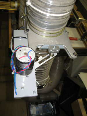
Other Types of Automatic Blastgate
The Next one looks like a linear guide.
But to make it inexpensive,the shafts are moulding spacers of concrete and the carrige is a stuck of plastic sheets .
The lead screw is used one whitch has 25mm leads per one turn.
I also use a old DC gear motor to drive the screw. That may be
24V DC 100mA
Gear Ratio 1: 80
80rpm
Torque 68.5mN/m
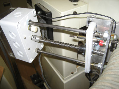
The Limit switches have a plastic bottun(white and red on the left picture),
pushed by the metal rods (6mm dia.) on the carrige.This type is easy to
adjust stop positions by metal rod lengh.
The motor and RL2 are in the sealed box.
I set this on a aluminum blastgate using a L shape aluminium angle.
Other electric parts and the circuit diagram are just the same with the
first type.
The left picture shows it's open state, and it takes about two seconds
both open and close.
The construction seems most solid.
The third type looks like ECOGATE.. The merit is need less motor torque
because the shatter is driven at the edge instead of the motor shaft.
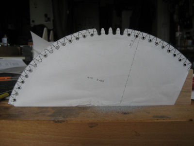
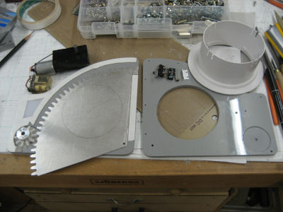
I made this shatter with tooth from hard aliminium(A5052) 1mm thick and
a motor gear from a plastic sheet 5mm thick.. I use a gear tooth drawing
by CAD(module 3,my freind made it for me) ,print on the paper,place them
on material sheets,dril holes at the bottom of tooth,cut roughly by very
fine saw ,then made final shape by files.
The base is a plastic sheet 6mm thick and to keep very narrow space for
the shatter movement, I used a plastc sheet(1mm thick ,same with the shatter)
positioning thin double-sided adhesive tape on both surface.Limit switches
are the type which have small roller on the hinge lever top.
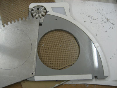
The left picture shows the open state.
Two limit switch rollers are to be inserted into holes on the base, switch
bodies are hold from the back side.
The shatter will push the close side limit switch rollers,but the openside
limit swith (on the left hole)is relased at the open state(not pushed like
close side), you have to exchange wire connections NO-NC of this switch.
The DC gear motor is from my junk box,so I don't know about specs. When
open or close,the shatter gear move 30 tooth , and motor gear have 10 tooth.
It means 3 turns of motor shaft is to be done.
On test running, it takes about 2 seconds .so the motor might rotate 1.5turn/s
--> 90 rpm.
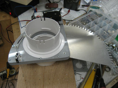
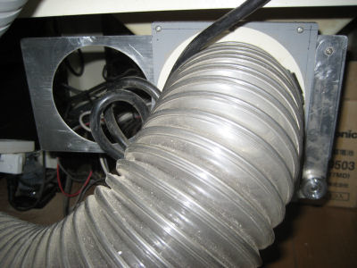
Pictures above show the completed figure ,(left-close,right-open). 100mm
dia. hose connectors are from a parts of home air ventilation.
For further development, I use a PIC chip and a DC motor drive IC for two
types below. By using them ,the motor protection ,Close delay time after
the machine shutt off ,limit switchless are done .

movie